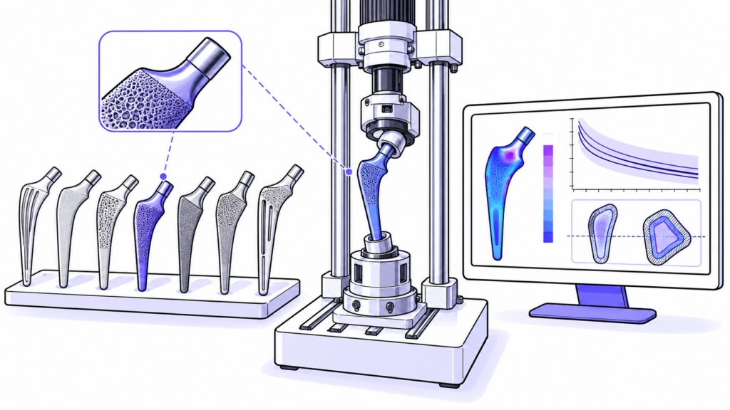
When a family of femoral stems includes different sizes, offsets, lengths, materials, or surface treatments, it is not always feasible to test all variants. The manufacturer must identify the configuration that subjects the design to the most demanding mechanical condition and justify why it represents the worst-case scenario. This decision affects the validity of the verification program, the number of samples, and the ability to extrapolate the results to the rest of the family.
Selecting the worst-case scenario does not automatically mean choosing the smallest shank. The critical combination depends on how geometry, material, manufacturing, and assembly affect stresses during cyclic loading. An early technical review helps prevent the lab from receiving samples that do not adequately cover the family or that require retesting once the design has been finalized.
What does “worst-case scenario” mean in a family of femoral stems?
The worst-case scenario is the reference or configuration most likely to exhibit the most unfavorable mechanical behavior with respect to the failure mode being evaluated. Therefore, the selection must be linked to the test objective and the risk being analyzed. One reference condition may be critical for fatigue in the rod body, while another may be critical for the neck region, a modular connection, or the adhesion of a coating.
ISO 7206-4 establishes a method for determining the fatigue resistance properties of stemmed femoral components under defined laboratory conditions. The standard specifies the placement, orientation, embedment, and loading, but the manufacturer remains responsible for justifying which specimens represent its product family. Therefore, the documentation must link the selection to the design, risk analysis, and available simulation results or exploratory test results.
Geometric factors that can make a reference point critical
Load-bearing cross-section and geometric transitions
A reduced cross-section typically increases stresses, but the critical point may be located at a transition, a change in radius, a groove, a window, or the beginning of a porous zone. It is necessary to examine not only the minimum area but also the local stress concentration and its position relative to the embedment level of the test.
Offset and neck length
A larger offset or a greater distance between the load center and the load-bearing axis increases the lever arm. This can increase the bending moment at the neck and in the proximal region. However, its effect must be analyzed in conjunction with the diameter, the cervicodiaphyseal angle, and the stiffness of the stem.
Length, curvature and orientation
Short, anatomical, curved, or anteverted stems may respond differently than a straight configuration. The orientation during implantation determines how flexion, compression, and torsion interact; therefore, a comparison based solely on commercial size may be insufficient.
| Variable | Possible mechanical effect | Useful evidence for the decision |
|---|---|---|
| Smaller cross-section | Higher nominal stresses and a lower fatigue margin | Drawings, cross-sectional areas and stress analysis |
| Larger offset | Longer lever arm and higher bending moment | Dimensional matrix and comparison of configurations |
| Small radius or notch | Local stress concentration | CAD detail, FEA and finish review |
| Short or curved stem | Change in stiffness and load distribution | Simulation and exploratory testing |
| Large porous area | Change in effective cross-section and surface finish | Coating and process specification |
Material, surface, and manufacturing process
Two parts with the same geometry may have different fatigue strengths if the alloy, heat treatment, surface finish, or manufacturing process differs. Polishing, shot blasting, machining, additive manufacturing, and porous coatings alter the surface and can introduce defects, residual stresses, or significant variations in thickness.
For additively manufactured designs, the build orientation, supports, post-processing, and the location of porous material must be included in the justification. If a family combines different processes or suppliers, it may be necessary to treat those variants as subfamilies and select a worst-case scenario for each manufacturing route.
How to Integrate Selection with Risk Analysis
The justification must be based on the failure mode: fracture of the body, failure at the neck, loss of a connection, or surface degradation. Next, the variables that increase the stress or reduce the strength are identified. This traceability prevents selection based on intuition and makes it possible to explain why the results are applicable to other designs.
- Define the failure mode and the objective of the test.
- Build a matrix of all dimensional, material and process variants.
- Compare lever arms, load-bearing cross-sections, radii and stress concentration areas.
- Use FEA, calculations or exploratory tests to rank configurations when the geometry is complex.
- Select the critical sample and document the limits of extrapolation to the rest of the family.
- Review the decision with the laboratory before manufacturing the final batch.
When it may be necessary to test more than one configuration
A single configuration does not always cover all risks. It may be reasonable to test more than one configuration when the family includes different materials, significant process changes, primary and revision stems, cemented and non-cemented designs, or geometries that shift the critical zone. There may also be a worst-case scenario for overall fatigue strength and another for the neck region.
In these scenarios, dividing the family into technically homogeneous groups typically provides a more solid justification than forcing a single representative sample. The decision must balance risk coverage, comparability, and cost, without reducing the evidence needed to demonstrate mechanical performance.
Information to Send to the Laboratory
- Drawings and CAD models of the candidate references.
- Dimensional table with size, offset, angles, length and relevant cross-sections.
- Materials, heat treatments, coatings and surface finishes.
- Description of the manufacturing routes and of any changes between references.
- Risk analysis, FEA results and data from previous tests.
- Intended use, test set-up configurations and proposed acceptance criteria.
With this information, the laboratory can review the method’s applicability, anticipate equipment needs, and verify whether the sample batch represents the critical condition. Conducting this review before finalizing the test design reduces the need for retests and ensures that the final report is consistent with the technical documentation.
Plan the test before manufacturing the samples
At Med-Lab IBV, we review the product family, critical configuration, and test conditions to help you build a solid technical justification. Contact our team to define the worst-case scenario and the validation program for your femoral stems.