The femoral component of a total knee replacement must maintain its integrity under repeated loads over millions of cycles. Although its geometry transmits the load through the condyles, certain situations involving reduced support can cause bending and stress concentrations in the intercondylar notch, the transition to the anterior flange, or other critical areas of the design.
Planning a test requires more than just selecting a standard. The manufacturer must justify which configuration represents the worst-case scenario, how the loading condition will be replicated, which test specimens will be comparable, and what criteria will be used to interpret a failure. The sooner these variables are defined, the more useful the test will be for optimizing the design and generating evidence for technical documentation.
What a fatigue test of the femoral component evaluates
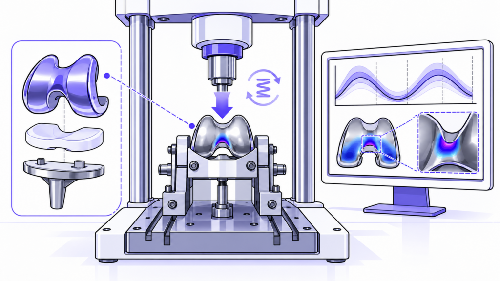
The objective is to characterize the component’s behavior under a controlled cyclic load and to identify modes of structural failure. ASTM F3210-22e1 describes a method for metal femoral components of total knee replacements under closed-condition testing. The load tends to reduce the intercondylar depth and creates a severe condition in which one condyle is unsupported.
This scenario allows for the comparison of designs tested under equivalent conditions, but it does not reproduce the full complexity of in vivo loads nor does it allow for a direct prediction of clinical lifespan. The value of the method lies in subjecting the component to a reproducible configuration, identifying weaknesses, and comparing materials, geometries, or manufacturing processes.
Why the implant’s geometry influences the test
CR, PS and revision designs
Components designed for posterior cruciate ligament preservation, posterior stabilization, or revision surgery have different geometries. Intercondylar sockets, posts, augmentations, and extensions alter stiffness and load transfer. Therefore, it should not be assumed that a single configuration automatically covers all variants within the product family.
Thickness and transition radii
Minimum wall thicknesses and radii in the intercondylar notch or at the transition between the condyle and the anterior rim can concentrate stresses. A small geometric change can alter the crack initiation point and the number of cycles to failure.
Material and manufacturing
The alloy, heat treatment, polishing, coatings, and additive manufacturing all influence strength. In porous or additively manufactured components, the build orientation and subsequent machining can be just as important as the nominal geometry.
| Aspect | Question for the manufacturer | Impact on the test plan |
|---|---|---|
| Design type | CR, PS, constrained or revision? | May require different groups and fixtures |
| Critical geometry | Where are the smallest thicknesses and radii? | Guides worst-case selection and inspection |
| Material | Are there different alloys or treatments? | May prevent results from being extrapolated between variants |
| Manufacturing | Does the supplier, build orientation or finish change? | May justify additional samples |
| Size | Is the smallest size also the least stiff? | Must be confirmed by calculation, FEA or other evidence |
How to Select the Worst-Case Scenario
The smallest size is often a candidate because of its reduced thicknesses, but it is not always the most unfavorable configuration. A larger design may incorporate a deeper housing, a different radius, or a transition with a greater lever arm. The analysis should compare the entire product matrix and focus on the failure mode that the test replicates.
A well-designed FEA can help organize the different scenarios and identify regions of maximum stress. It should use material properties, contacts, constraints, and loads that are consistent with the physical test. Its purpose is not to automatically replace the test, but to provide a traceable basis for selecting specimens and understanding the results.
Variables that must be agreed upon before starting the test
- Implant configuration and the exact reference that represents the worst case.
- Component orientation and support condition in the fixture.
- Magnitude, ratio and frequency of the cyclic load.
- Number of samples and load-level strategy.
- Preconditioning and environmental conditions, where relevant.
- Failure, run-out and post-test inspection criteria.
- Information the report must include to ensure traceability.
What may be considered a failure during the test
A complete fracture is an unambiguous result, but it is not the only indicator. The appearance of a crack, a permanent deformation that compromises function, displacement within the fixture, or a loss of integrity in a porous area may require stopping the test and analyzing the specimen. The criteria must be defined before testing and kept consistent when comparing variants.
After the test, visual and dimensional inspection can be supplemented with fracture analysis or nondestructive testing techniques. Correlating the failure location with FEA predictions and geometry helps distinguish between a design weakness, a manufacturing effect, and an experimental setup issue.
Physical Testing and Simulation: Complementary Functions
Simulation allows us to explore more variants than it would be reasonable to test physically. Physical testing, on the other hand, incorporates actual geometry, tolerances, surface roughness, and variations in the manufacturing process. Integrating both sources of evidence improves the selection of the worst-case scenario and facilitates the interpretation of differences between prototypes.
For the comparison to be valid, there must be consistency between the model and the actual assembly. The boundary conditions, the load application point, and the support areas must match. If the tooling or orientation is modified, the model and the justification for its applicability should also be reviewed.
Errors That May Require the Test to Be Repeated
- Choosing the smallest size without comparing the full geometry of the family.
- Not documenting the batch, material, finish or manufacturing process of each sample.
- Defining the fixtures once the parts have already been manufactured.
- Changing failure criteria during the test campaign.
- Extrapolating results between CR, PS or revision designs without a mechanical justification.
- Interpreting the number of cycles as a direct equivalent of years of clinical life.
What information should be provided to the laboratory
The laboratory should receive drawings, CAD models, a matrix of sizes and configurations, materials, finishes, manufacturing processes, FEA results, risk analyses, and test records. It must also be aware of the regulatory objective and whether the campaign is intended to compare prototypes, verify a final design, or justify a change.
This preliminary review makes it possible to confirm the feasibility of the assembly, manufacture appropriate tooling, and establish an efficient loading sequence. In addition, it helps ensure that the final report clearly describes the sample, the method, any deviations, and the results, which the manufacturer will include in its technical dossier.
Define a fatigue test campaign suitable for development
At Med-Lab IBV, we help you review the worst-case scenario, the setup, and the evaluation criteria before beginning testing of knee femoral components. Contact our technical team to design a testing plan that aligns with your product and your validation goals.